Page 15 - ACS 24-UHF Eagle with MTC User Manual
P. 15
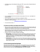
In the Bridge program, after selecting the tty listing under COM 1, be sure to click on Save at the bottom of
that window:
Select the tty
connection here.
Then, click on Save.
Go to your Applications folder and hold the Ctrl key while clicking on the MTC icon. Choose Open from
the drop-down menu.
Enter the registration number you received when you registered the software.
If you lose your registration number and you need to install MTC onto another computer, please go to the
following link to have it emailed to you:
http://make-the-cut.com/LostRegKey.aspx
You may now skip to Section 1.11.
1.10 Connecting the ACS to Your Computer under Windows
Place your cutter on a sturdy horizontal surface. If you have not yet done so, attach the bolt-on tables to the
cutter (refer to the instructions in Section 1.08.) If you are not going to use the tables, then be sure to allow
enough free room in both the front and the back for the mat to extend during cutting.
Connect the power cord to the left side of the cutter and plug into a wall outlet or power strip. Turn on the
power using the power switch on the left side. The yellow LED display should come on and the cutter will
initialize (carriage will move to the far right side of the cutter).
Connect your cutter to your computer using either of the following:
USB Connection: Turn off the cutter and connect the USB cable to the right side of the cutter and into
an available USB port on your computer. Turn on the cutter. The Windows Hardware Manager will
identify the USB connection. If the Hardware Installation window pops open, proceed and accept all
defaults. On the Control Panel, press the Menu button and verify that the Baud Rate is set to 57600.
Refer to Section 1.05, Step 4.
Serial Connection: Turn off the cutter and connect the RS232 cord to the right side of the cutter and
into the serial port on your computer. Turn on your cutter. The Windows Hardware Manager will identify
the USB connection. On the Control Panel, press the Menu button and change the Baud Rate to 9600.
Refer to Section 1.05, Step 4.
1.11 Verify Communication and Test Draw Shapes
New owners tend to be VERY eager to try out their cutter. It’s also important to test your cutter to ensure that
data is being sent properly from your computer to the cutter. The following steps will allow you to do some
testing with the pen tool. But note that the following steps are for DRAWING, not cutting. Before inserting
the blade tool into your cutter, please read the following Sections: 1.05, 1.06, 1.07, and 2.01.
15