Page 198 - ACS 24-UHF Eagle with MTC User Manual
P. 198
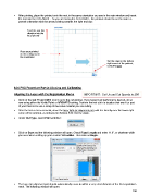
After printing, place the printout onto the mat, in the same orientation you see in the main window and insert
the mat into the ACS-24UHF. As you are facing the ACS-24UHF, the printout should be on the mat in a
portrait orientation with the arrow pointing towards the right end cap:
Feed the mat this
direction into the
ACS-24UHF
Place your printout
on the cutting mat in
this orientation.
Set the origin in the bottom
right corner of the printout,
using the laser
9.04 PNC Procedure Part 2: Aligning and Calibrating
Aligning the Laser with the Registration Marks IMPORTANT: Set Us and Cut Speeds to 200
Click on the Cut Project With icon to go to the cut window. If you haven’t yet performed a test cut, do so
now using either the Knife Point or WYSIWYG setting. Perform the test cut in a location that won’t be part
of your final cut or use a scrap of the same material you are cutting.
After the test cut is successful, move the laser light (or alignment pin) until it is directly over the lower right
corner of the printout, as indicated in Section 9.03. Set the origin.
Under Cut Type, select Print and Cut:
Click on Start and the following window will open. Check Fixed Length and enter 11.0”, or whatever width
you used when setting up your custom Virtual Mat. Then click on Begin.
The laser (or alignment pin) should automatically move to within a very short distance of the first registration
mark. The following window will open:
198